 ar
ar bg
bg hr
hr cs
cs da
da nl
nl fi
fi fr
fr de
de el
el hi
hi it
it ko
ko no
no pl
pl pt
pt ro
ro ru
ru es
es sv
sv tl
tl iw
iw id
id lv
lv lt
lt sr
sr sk
sk sl
sl uk
uk vi
vi et
et hu
hu th
th tr
tr fa
fa ms
ms hy
hy ka
ka ur
ur bn
bn mn
mn ta
ta kk
kk uz
uz ku
ku
load cell wiring schematic
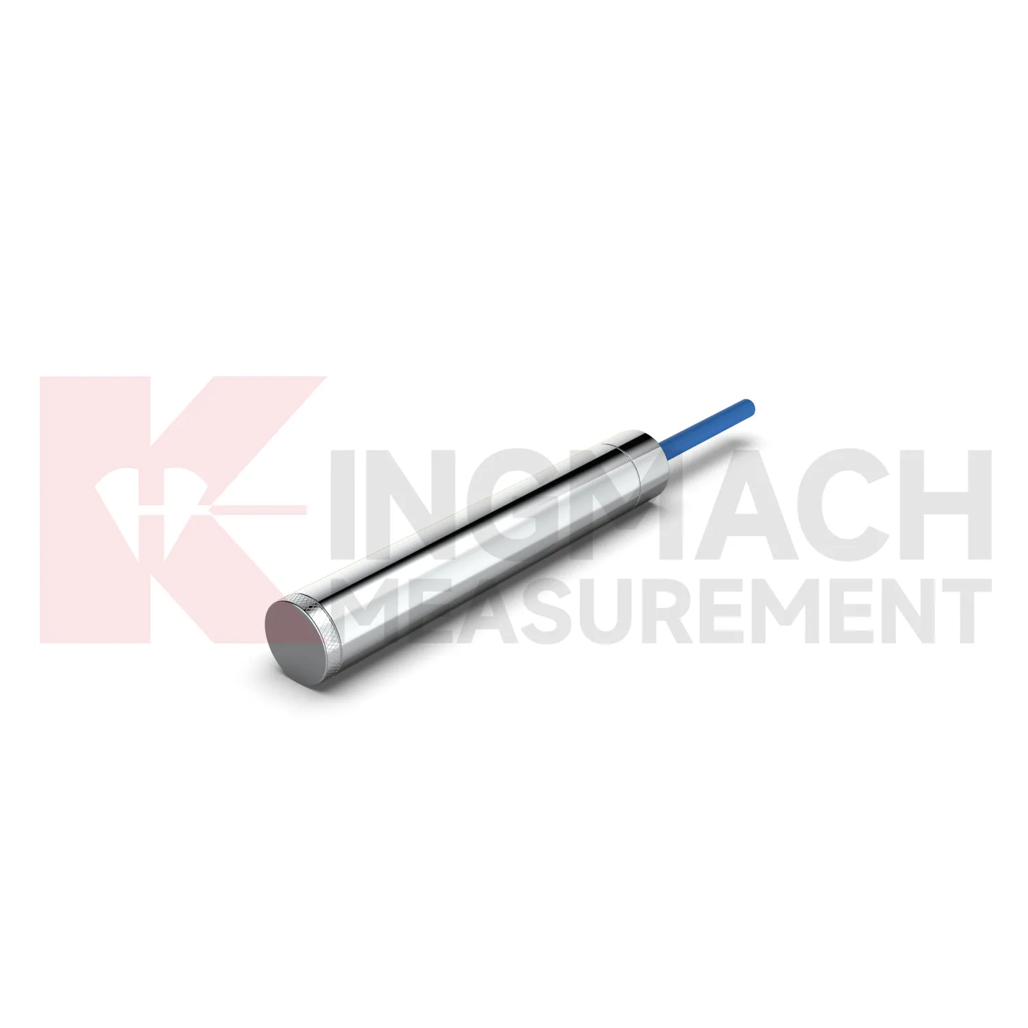
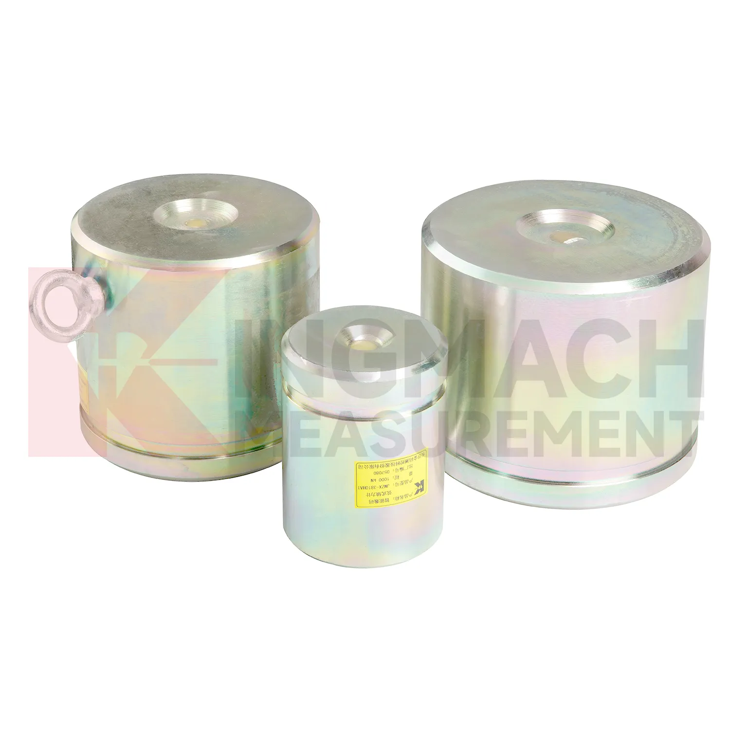
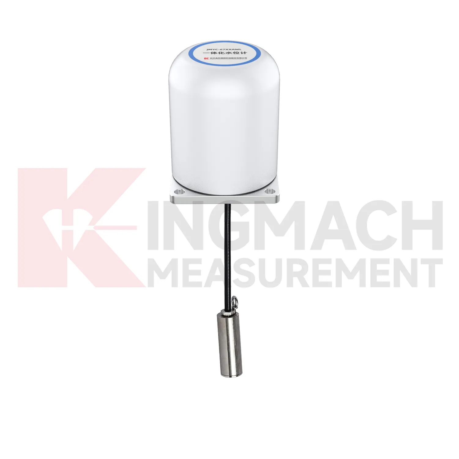
Kingmach load cell wiring schematic can also include pressure related sensing where soil or structural contact pressure is the main concern. The JMZX-50XXAT/ATM earth pressure cell family is listed in 0.3 MPa, 0.6 MPa, 1 MPa, 2 MPa, 4 MPa, 6 MPa, and 8 MPa ranges, with 0.001 MPa pressure resolution, 0.5%FS pressure accuracy, and ±0.5°C temperature accuracy. The product information also refers to high strength elastic steel, waterproof and durable construction, a 50 year design life, 800 stored measurement sets, and automated acquisition support. For retaining structures, embankments, dams, tunnels, and foundation pits, those pressure records help engineers understand whether earth load, water influence, compaction, or excavation stage changes are affecting the structure. Kingmach's broader monitoring catalog allows these readings to be compared with settlement, water pressure, displacement, and tilt. That connection is important because pressure change without movement may still indicate a developing load redistribution that deserves closer inspection. The same site places these instruments within a wider monitoring range, including piezometers, water level meters, displacement transducers, settlement sensors, tiltmeters, cables, data loggers, and software. That wider range helps when a project needs force data to be compared with movement, water, and temperature records.
Application of load cell wiring schematic
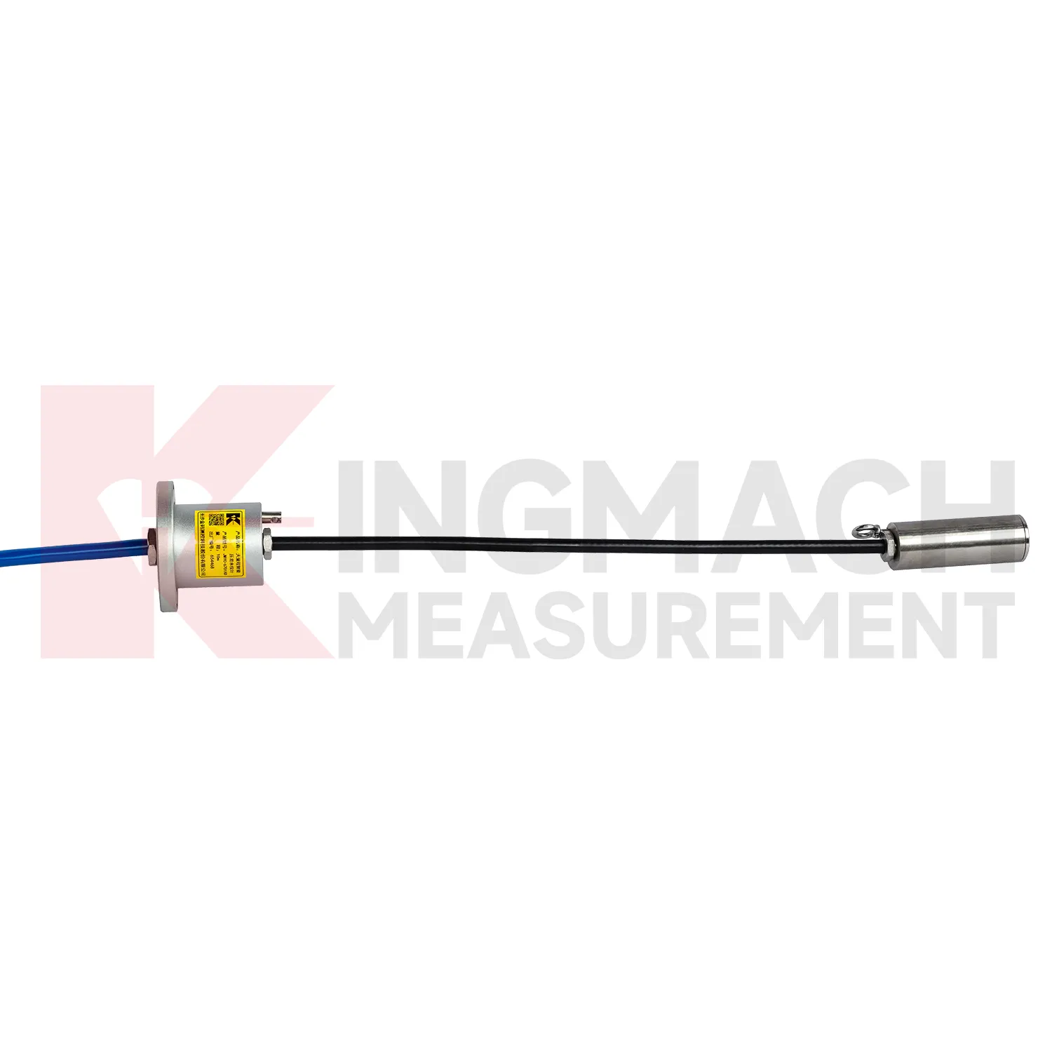
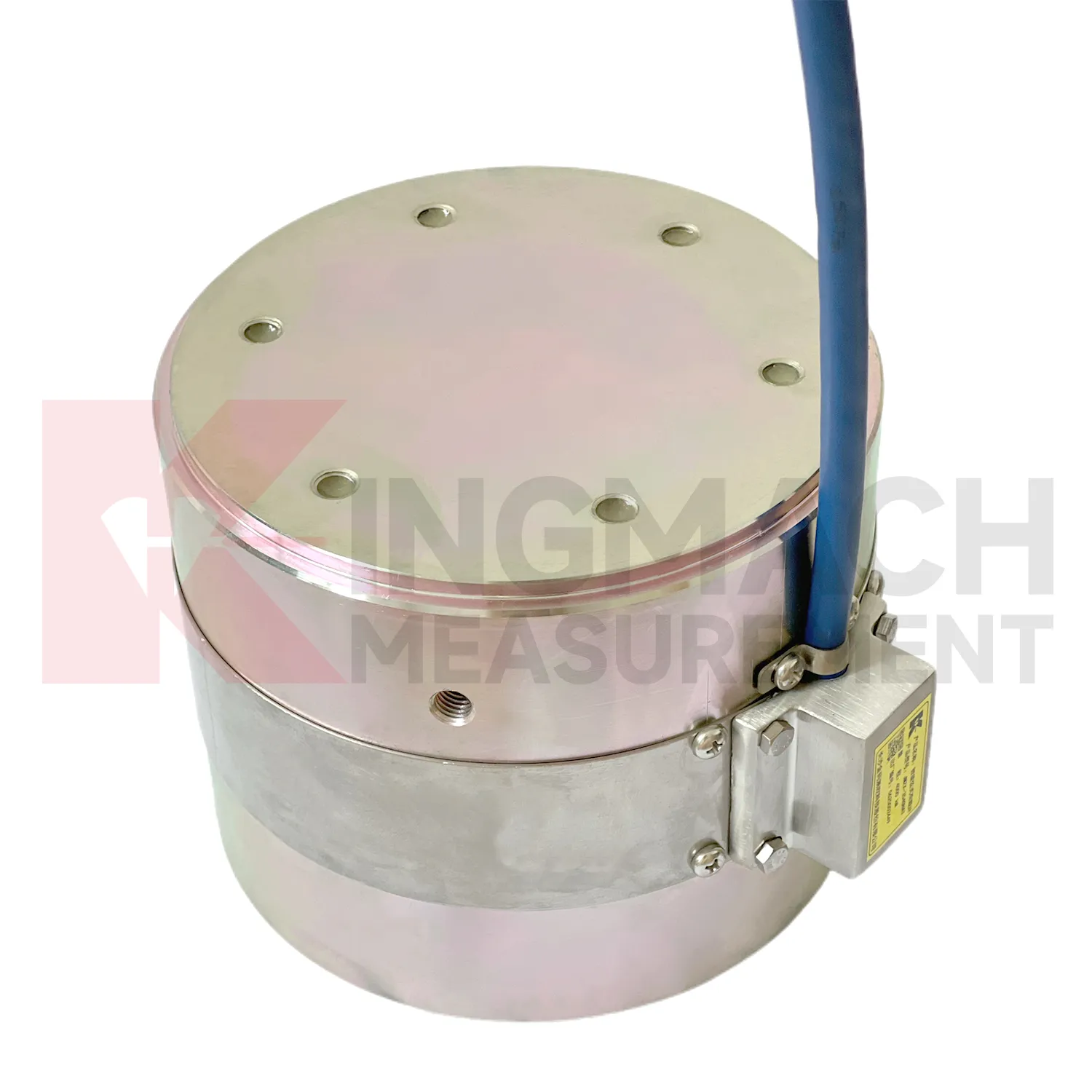
In dam and hydropower monitoring, load cell wiring schematic can be used for anchor force, concrete bearing pressure, gate structure load checks, earth pressure near embankments, and long term load review around seepage control areas. The monitoring difficulty is durability. Access may be limited, water influence is persistent, and seasonal temperature changes can mask small force trends. Kingmach hollow load cells list a 50 year design life, waterproof durability, automatic temperature correction, digital output, and 800 stored measurement records. Earth pressure cells also list a 50 year design life, 0.5%FS pressure accuracy, and ±0.5°C temperature accuracy. These parameters support long observation periods, especially when readings are tied to reservoir level, seepage, rainfall, and temperature records. For dam owners, a single force value is rarely enough. The trend should show whether anchors remain stable, whether pressure increases after impoundment, and whether unusual readings appear near maintenance or water level changes. Automated acquisition is often worth planning where manual access is costly. For long service assets, the monitoring plan should also say who checks the reading after storms, earthquakes, reservoir level changes, or maintenance work. A sensor that is never reviewed at the right moment does not give the owner much protection.
The future of load cell wiring schematic
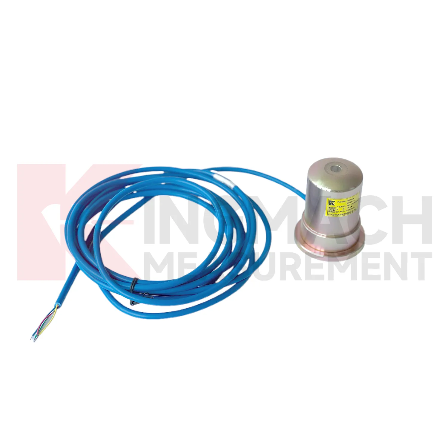
As monitoring standards become more detailed, load cell wiring schematic will be expected to support both engineering judgment and audit trails. Owners want to know whether a force change is real, when it began, how it compares with design stages, and what action followed. Kingmach load products already include technical features such as 0.5%FS precision on major force models, temperature correction, waterproof construction, direct kN display on axial force meters, and stored measurement records on smart designs. Future systems can tie these details to inspection workflows, maintenance orders, and asset management platforms. That means a load reading will not sit alone in a spreadsheet. It will connect to the sensor model, calibration certificate, installation photo, cable route, alarm history, and nearby movement data. Wireless links and AI screening may speed review, but the foundation remains disciplined measurement. The future belongs to force monitoring records that can be checked, repeated, and understood years after installation.
Care & Maintenance of load cell wiring schematic
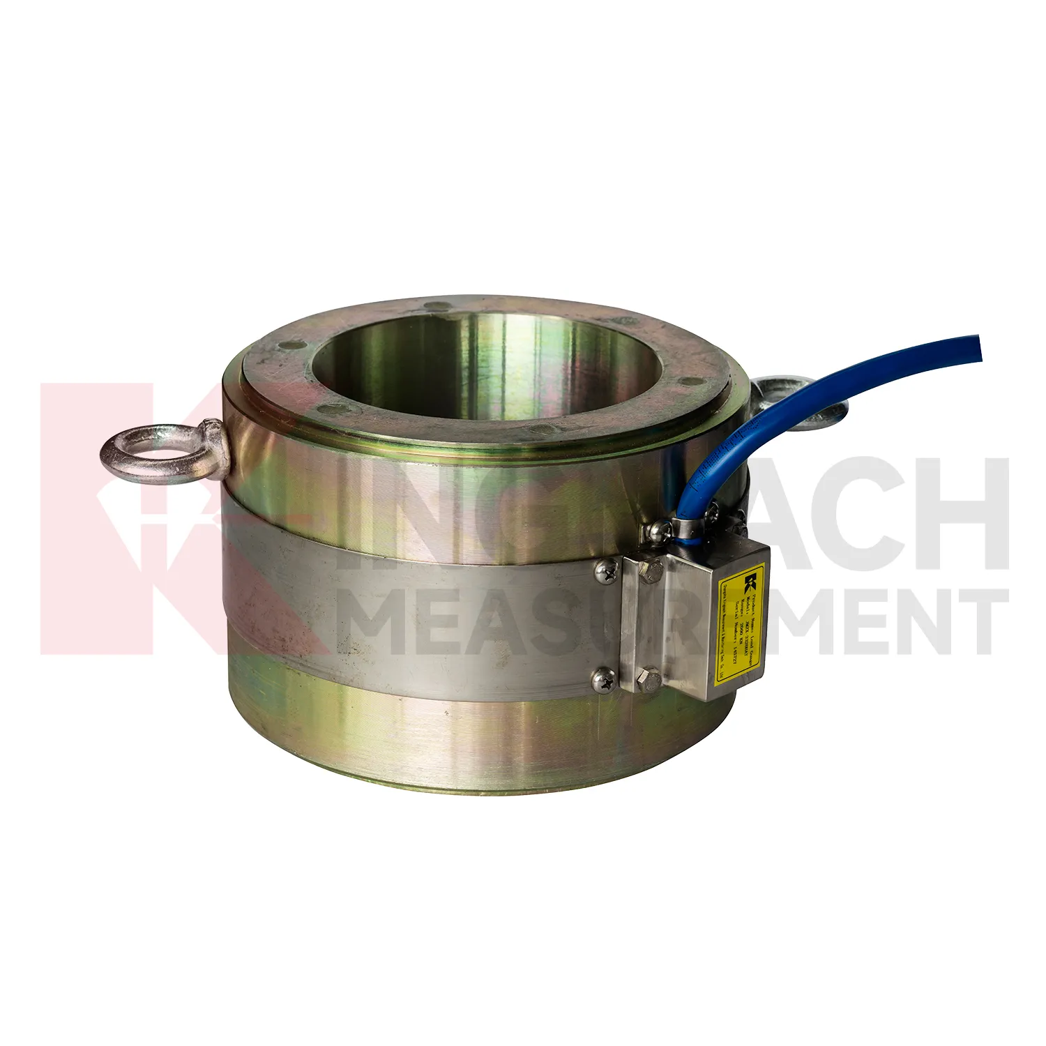
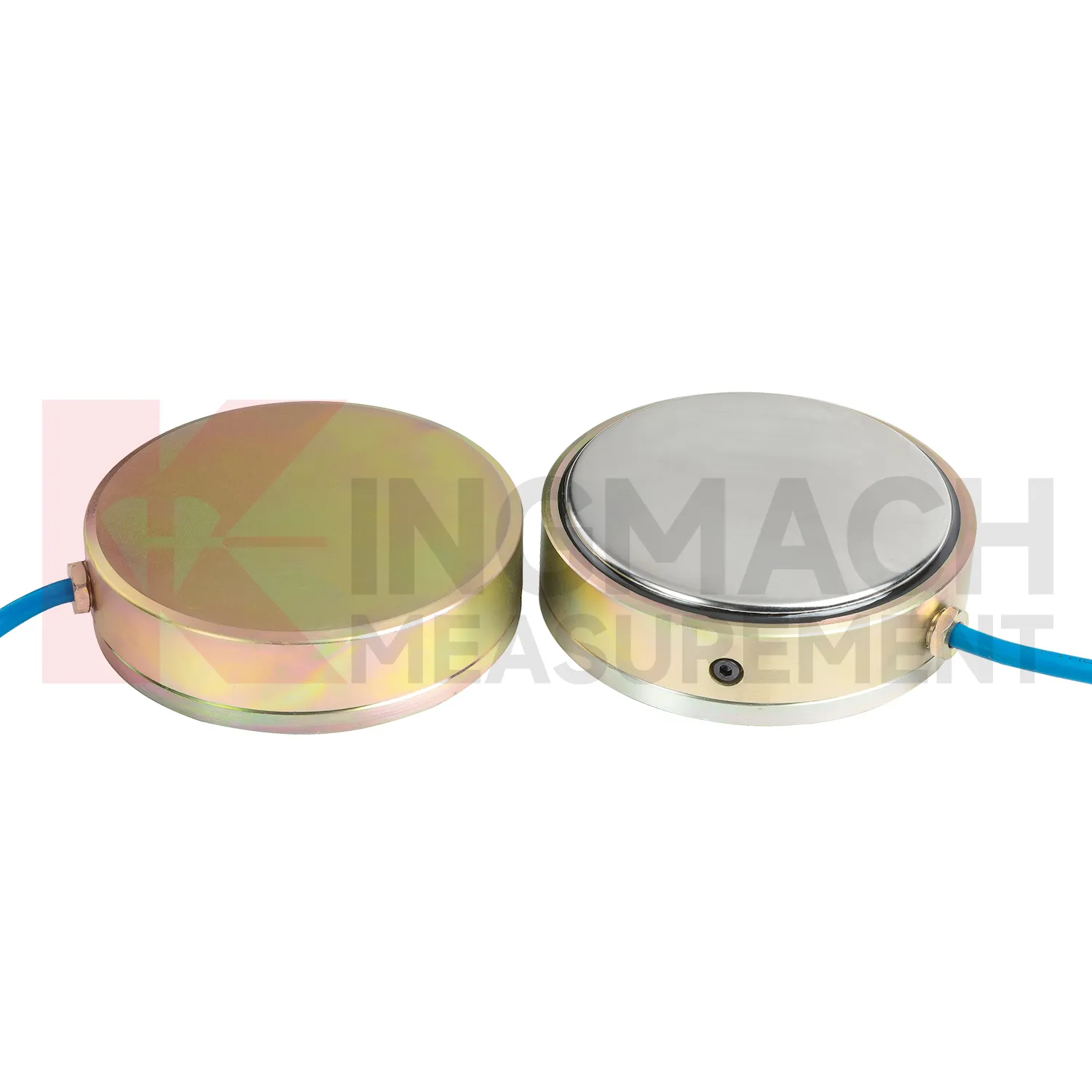
For load cell wiring schematic used in bridge cable or anchor monitoring, maintenance should focus on the load path and the environment around the sensor. Hollow load cells list 500 kN to 8000 kN ranges, temperature correction, waterproof durability, and 800 stored measurement records on smart models. These features support long term observation, but they do not replace site checks. During installation, make sure the washer, bearing plate, anchor head, and sensor axis are properly seated. Record the first stable force after locking and keep the temperature reading with it. During operation, inspect cable protection, connector sealing, corrosion exposure, and any change near the anchor zone. Compare force records after seasonal temperature shifts, heavy traffic periods, maintenance work, or extreme weather. If one point changes while nearby points remain stable, check the bearing surface and wiring before treating the reading as structural behavior. A clean maintenance log helps separate sensor issues from real force redistribution.
Kingmachload cell wiring schematic
load cell wiring schematic supports decisions that are too important to leave to visual inspection alone. A bridge anchor plate may look unchanged while force redistributes between strands. A deep excavation support may still be straight while axial load rises. A pile test may appear steady while the loading system introduces eccentric force. Kingmach's load monitoring range gives engineers several instrument formats for these different questions, including hollow, solid, axial force, and pressure related products. The field value depends on repeatability. A reading taken today must be comparable with the first stable reading, the next load stage, and the record after temperature changes. That is why calibration coefficients, zero values, cable labels, installation photos, and compatible readouts matter. When all of those details are controlled, force monitoring becomes a practical inspection record rather than a one-time test result. That discipline turns a single load point into evidence that can be reviewed months later.
FAQ
Q: How can load cell wiring schematic be connected to a monitoring platform? A: Use compatible readouts, acquisition modules, data loggers, DTUs, and software platforms according to site access, cable distance, power, and reporting requirements. Q: What makes smart models useful in large networks? A: Stored model data, calibration coefficients, zero values, temperature data, and measurement records reduce confusion across many channels. Q: Should manual readings still be kept? A: Yes, manual checks are useful after installation, maintenance, abnormal alarms, or logger changes. Q: How should alarm limits be set? A: Base them on design stage, sensor range, expected load change, temperature behavior, and nearby monitoring points. Q: What data should be reviewed together with force? A: Settlement, displacement, tilt, water level, pore pressure, rainfall, temperature, construction events, and inspection notes.
Reviews
Andrew Lee
The visualization software is intuitive and powerful. It helps us analyze monitoring data efficiently.
Christopher Martinez
Very satisfied with the readouts & data loggers. User-friendly interface and supports multiple sensor inputs.
Latest Inquiries
To protect the privacy of our buyers, only public service email domains like Gmail, Yahoo, and MSN will be displayed. Additionally, only a limited portion of the inquiry content will be shown.
Charlotte***@gmail.comUnited Arab Emirates
Hi, we require instrumentation cables suitable for harsh environments. Could you advise on specifica...
Mia***@gmail.comNetherlands
Dear team, we are interested in your readouts & data loggers compatible with multiple sensors. Do yo...