
 EN
EN
 ar
ar bg
bg hr
hr cs
cs da
da nl
nl fi
fi fr
fr de
de el
el hi
hi it
it ko
ko no
no pl
pl pt
pt ro
ro ru
ru es
es sv
sv tl
tl iw
iw id
id lv
lv lt
lt sr
sr sk
sk sl
sl uk
uk vi
vi et
et hu
hu th
th tr
tr fa
fa ms
ms hy
hy ka
ka ur
ur bn
bn mn
mn ta
ta kk
kk uz
uz ku
ku
Real-Time Dam Safety Alerts with Differential Pressure Water Level Sensors
Key Takeaways An alert chain needs more than a sensor: define field in...

Load Cell Wire Diagram: Straightforward Wiring Steps
A load cell wire diagram is often the first thing you reach for when a new sensor arrives — and for good reason. Even seasoned technicians run into mix‑ups between red and black excitation leads or swapped signal wires. Kingmach Measurement & Monitoring Technology Co., Ltd. ships every load cell with a dedicated wiring sheet, but field conditions sometimes demand a quick reference. Most of our sensors follow the common 4‑wire color convention: red for excitation+, black for excitation‑, green for signal+, and white for signal‑. Six‑wire variants add blue and yellow sense lines, which compensate for voltage drop in long cable runs. Whether you are retrofitting a geotechnical monitoring system or building a test stand, getting the connections right from the start avoids drifting zero points and overload damage. This page lays out the basics of a load cell wire diagram and explains how to match it to your instrument, so you can spend less time troubleshooting and more time collecting reliable data.
Technical Detail
Kingmach Measurement & Monitoring Technology Co., Ltd. has built a reputation around practical sensor engineering, so we understand that a clear load cell wire diagram saves more time than any manual full of footnotes. As a mid‑range brand with distribution in over 40 countries, we keep our wiring straightforward. Our standard strain‑gage load cells typically use a four‑conductor shielded cable, color‑coded to industry norms: red and black for excitation (often 5–15 V), green and white for the millivolt signal. For six‑wire models, two extra sense leads (blue and yellow) feedback the actual bridge voltage, which becomes important when cable runs exceed 10 meters. Because we serve geotechnical, structural, and industrial monitoring projects, varied junction boxes, data loggers, and PLCs come with their own terminal labels; a side‑by‑side diagram helps align pinouts without guesswork. Ordering from Kingmach means you receive documentation that matches each sensor’s serial number — not a generic leaflet. If your application needs a non‑standard connector or reversed polarity, our engineers can provide a modified load cell wire diagram before the unit leaves the factory. We also keep a library of application notes on topics like shield grounding (connect at one end only to avoid ground loops) and troubleshooting open‑circuit readings. Beyond the diagram, we back every order with direct technical support, so a quick call or email can solve configuration questions. Whether you are setting up a single point or a multi‑cell array, starting with the right wiring eliminates common headaches: zero return errors, signal drift, and noise from improper shielding. Our product range spans low‑profile compression canisters, S‑type tension cells, and custom‑shaped sensors, but the underlying wiring logic remains consistent. By combining a tested load cell wire diagram with reliable sensing elements, you can focus on the data that matters for your project.
News
Key Takeaways An alert chain needs more than a sensor: define field in...
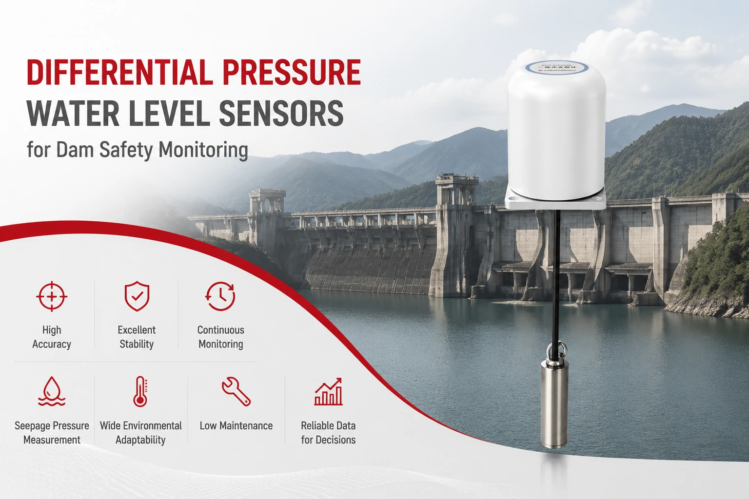
Key Takeaways The strongest fit is usually a confined, submerged, or s...
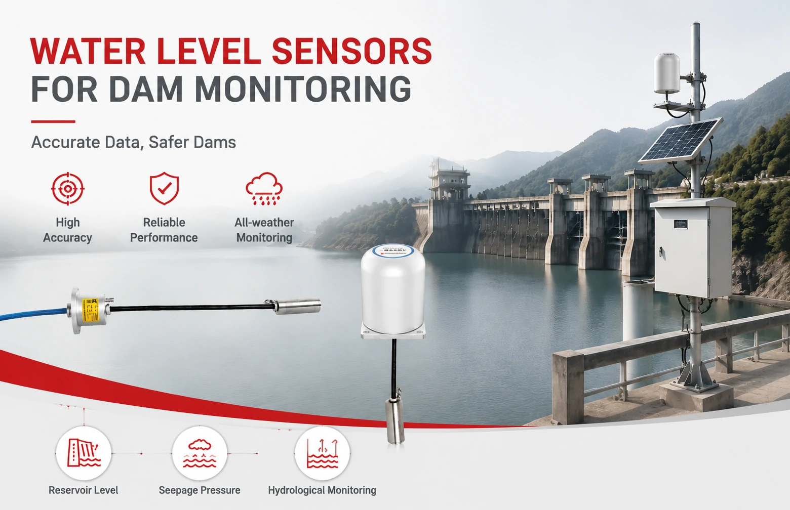
Kingmach Water Level Sensors for Dam Monitoring: A Buyer's Guide to Differential Pre...
Products
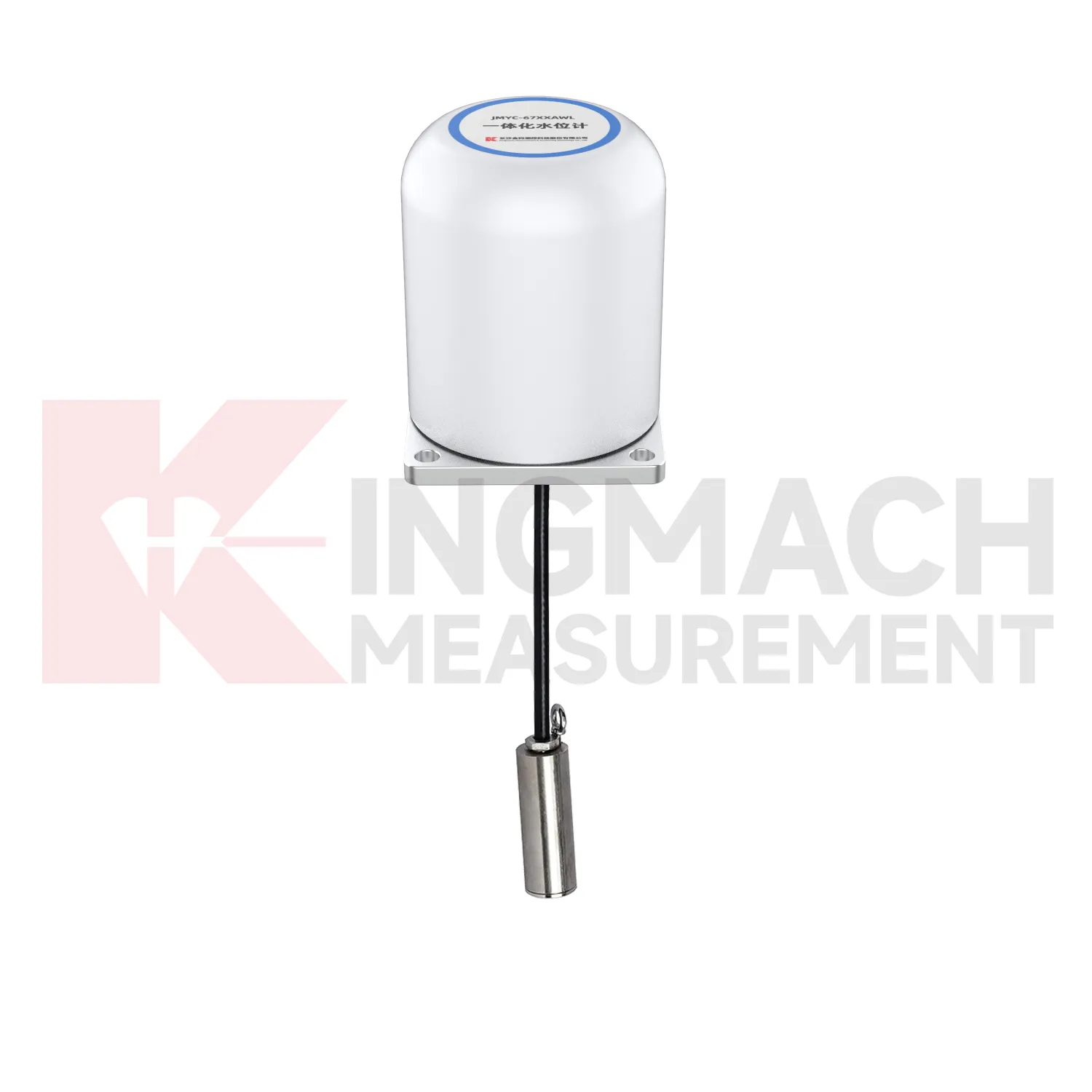
Integrated Wide-Range Differential Pressure Water Level Meter JMYC-67XXAWL
View Details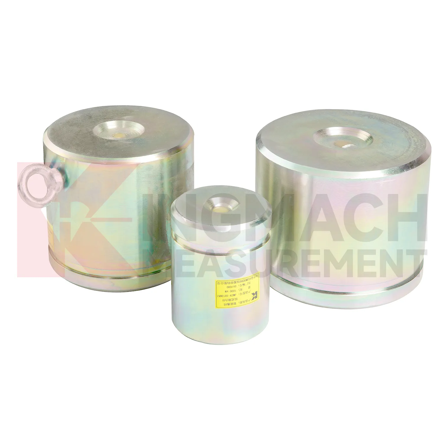
Axial Force Load Meter ( VW & Smart Type)JMZX-38XXHAT
View Details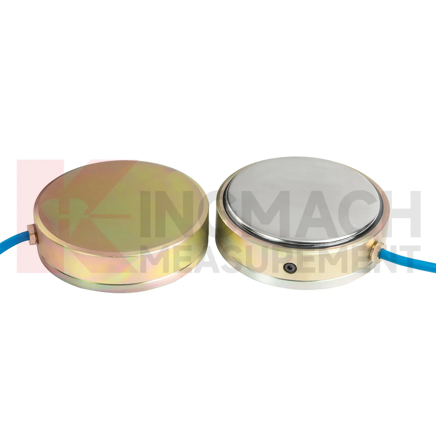
Earth Pressure Cell ( VW & Smart Type) JMZX-50XXAT/ ATM
View DetailsFAQ
Most manufacturers follow a similar convention — red and black for excitation, green and white for signal — but it is not universal. Kingmach includes a specific wire diagram with each sensor, and you can request a PDF copy if yours is lost. Always check the supplied sheet rather than assuming a color assignment.
A 6‑wire configuration carries separate sense leads that measure the actual excitation voltage at the bridge. This removes the effect of cable resistance, which matters in long runs, temperature‑variable environments, or high‑precision weigh systems. If your cable length exceeds 10–15 meters, a 6‑wire setup is typically worth the extra two wires.
With a multimeter, measure resistance between excitation leads — typically 350 Ω or 700 Ω for the bridge. The signal output should show near‑zero millivolts with no load. If the reading is negative or drifts wildly, you may have swapped signal wires or damaged the cell. Kingmach support can walk you through these checks if needed.
Yes. If your data acquisition system uses a non‑standard connector or pin assignment, we can build the sensor with a matching cable and provide a tailored load cell wire diagram. This service avoids rewiring on site and is available for most of our geotechnical and industrial cells.
Share your product type, target capacity, and application requirements. Our team can review the details and recommend a practical next step.
If you are interested in our products or want to become our partner.
Please leave your contact information, our team will contact you as soon as possible.
Mail: [email protected]
Contact Us: +8613808434127
Address: No. 188 Tongzipo West Rd, Changsha, Hunan, China